Thermal Vacuum Chamber (TVC) Design
As part of capacity-building efforts for satellite testing infrastructure in Nepal, I contributed to the preliminary design of a Thermal Vacuum Chamber (TVC) intended for environmental qualification testing of CubeSats up to 6U configuration.
A thermal vacuum chamber replicates the extreme vacuum and thermal conditions encountered in low Earth orbit. The objective of this project was to design a structurally sound, thermally capable, and economically feasible chamber suitable for small satellite validation within Nepal.
Project Objective
The primary goal was to develop a compact TVC capable of performing:
- Thermal Vacuum Test (TVT)
- Thermal Cycling Test
- Thermal Balance Test
The system was designed to simulate:
- Internal pressure: ~10⁻⁴ torr
- Temperature range: −100°F to 220°F
- External atmospheric pressure loading under vacuum conditions
System Architecture
The TVC was subdivided into three major subsystems:
- External Pressure Vessel
- Heating and Cooling System (Cryoshroud)
- Vacuum System
External Pressure Vessel Design
The chamber was designed as a cylindrical pressure vessel subjected to external atmospheric pressure, following ASME Boiler and Pressure Vessel Code (Section VIII).
Design Specifications:
- Length: 900 mm
- Diameter: 900 mm
- Material: 304 Stainless Steel
- Modulus of Elasticity: 193 GPa
- Compressive Strength: 205–310 MPa
Thickness calculations were performed iteratively under three configurations:
- Without reinforcement
- With one reinforcement
- With two reinforcements
A thickness of 2 mm was determined to safely withstand the design pressure.
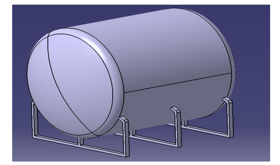
Fig: CAD model of cylindrical pressure vessel subjected to external atmospheric pressure.
Head Selection and Structural Validation
Three head configurations were analyzed:
- Flat head
- Spherical head
- Tori-spherical head
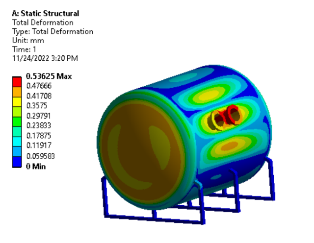
Finite Element Analysis (FEA) was conducted in ANSYS Mechanical.
Results showed:
- Flat and spherical heads failed at shell intersection
- Tori-spherical head exhibited maximum Von Mises stress of 143.98 MPa
- Maximum deformation: 0.448 mm
- Full assembly deformation (with cutouts): 0.536 mm
The tori-spherical head was selected due to its superior structural integrity under external pressure loading.
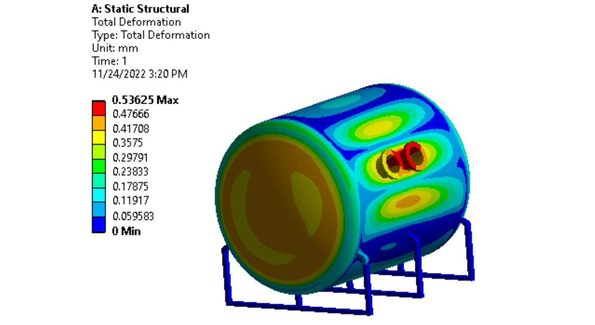
Fig: Finite Element Analysis showing stress distribution under external pressure.
Heating and Cooling System (Cryoshroud Design)
To simulate orbital thermal conditions, an internal cryoshroud system was developed.
Heating System
- Conductive heating selected for simplicity
- Three 475 W strip heaters (240V)
- Copper platen for uniform heat distribution
- K-type thermocouples for feedback control
A closed-loop temperature control strategy was proposed for automated regulation.
Cooling System
Radiative cooling was implemented using liquid nitrogen circulation.
Two design concepts were evaluated:
- Helical pipe configuration
- Multi-circular loop configuration
The circular pipe design was selected for ease of manufacturability and integration.
Final Cryoshroud Parameters:
- Radius: 350 mm
- Length: 850 mm
- Aluminum alloy thermal shroud
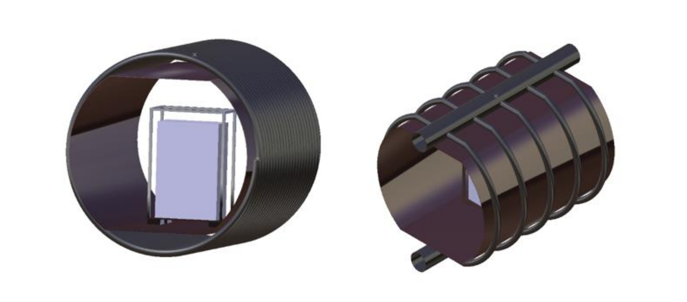
Fig: CAD model of cryoshroud assembly for heating and radiative cooling simulation.
Thermal Analysis
Steady-state thermal analysis was conducted in ANSYS.
Modeling included:
- Conductive heat transfer (heater to satellite)
- Radiative cooling (shroud to satellite)
- Thermal emission between components
Simulation results demonstrated achievable surface temperatures up to 46°C on the satellite model, validating heating system feasibility.
Vacuum System Design
The vacuum system was designed to achieve required low-pressure conditions using:
- Roughing pump
- Turbo pump
- Vacuum gauges
- Isolation valves
- Residual Gas Analyzer (RGA)
Engineering Contributions
This project demonstrates:
- Pressure vessel design under external loading (ASME methodology)
- Head configuration comparison and FEA validation
- Integrated thermal system design (heating + LN2 cooling)
- Cryoshroud structural and thermal modeling
- Vacuum system architecture planning
- CAD modeling in CATIA
- Structural and thermal simulation in ANSYS
The proposed TVC design represents an important step toward establishing indigenous satellite environmental testing capability within Nepal.