Engineering Design and Structural Validation
The facility consists of a 2 m glass tank, a rigid structural frame, and a gantry-driven flat plate actuation mechanism. Blockage ratio constraints were imposed to maintain aerodynamic fidelity below 5%, ensuring minimal wall interference on flow development. Structural integrity of the tank under hydrostatic loading was verified using finite element analysis, leading to a 10 mm glass thickness selection with a safety factor of approximately 15. The actuation system was powered by a bipolar stepper motor controlled via ESP8266 and L298N driver circuitry, enabling precise velocity control and repeatable Reynolds number targeting. This ensured dynamic similarity and controlled transient flow initiation.
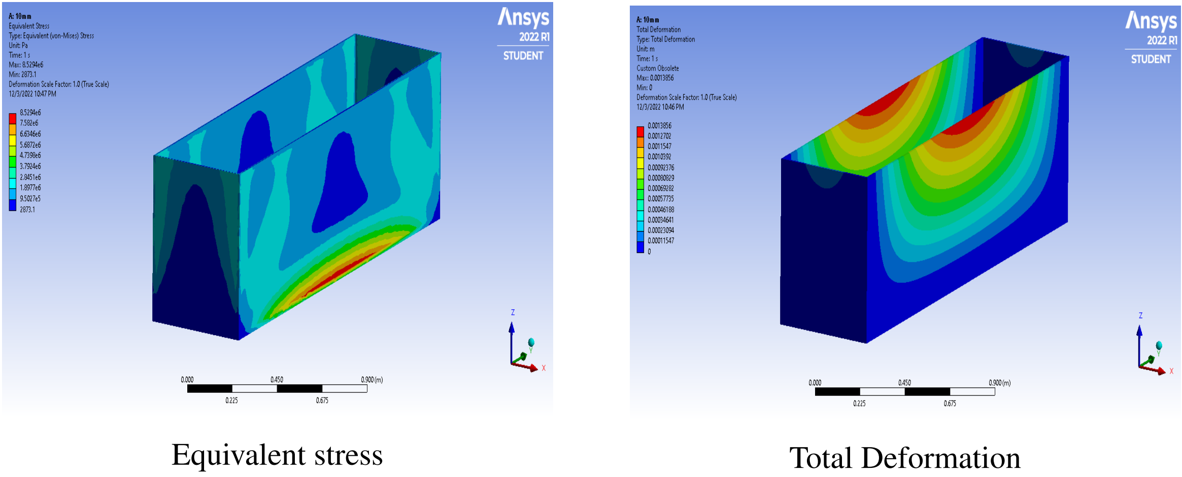
Fig: FEA stress & deformation contour of tank.
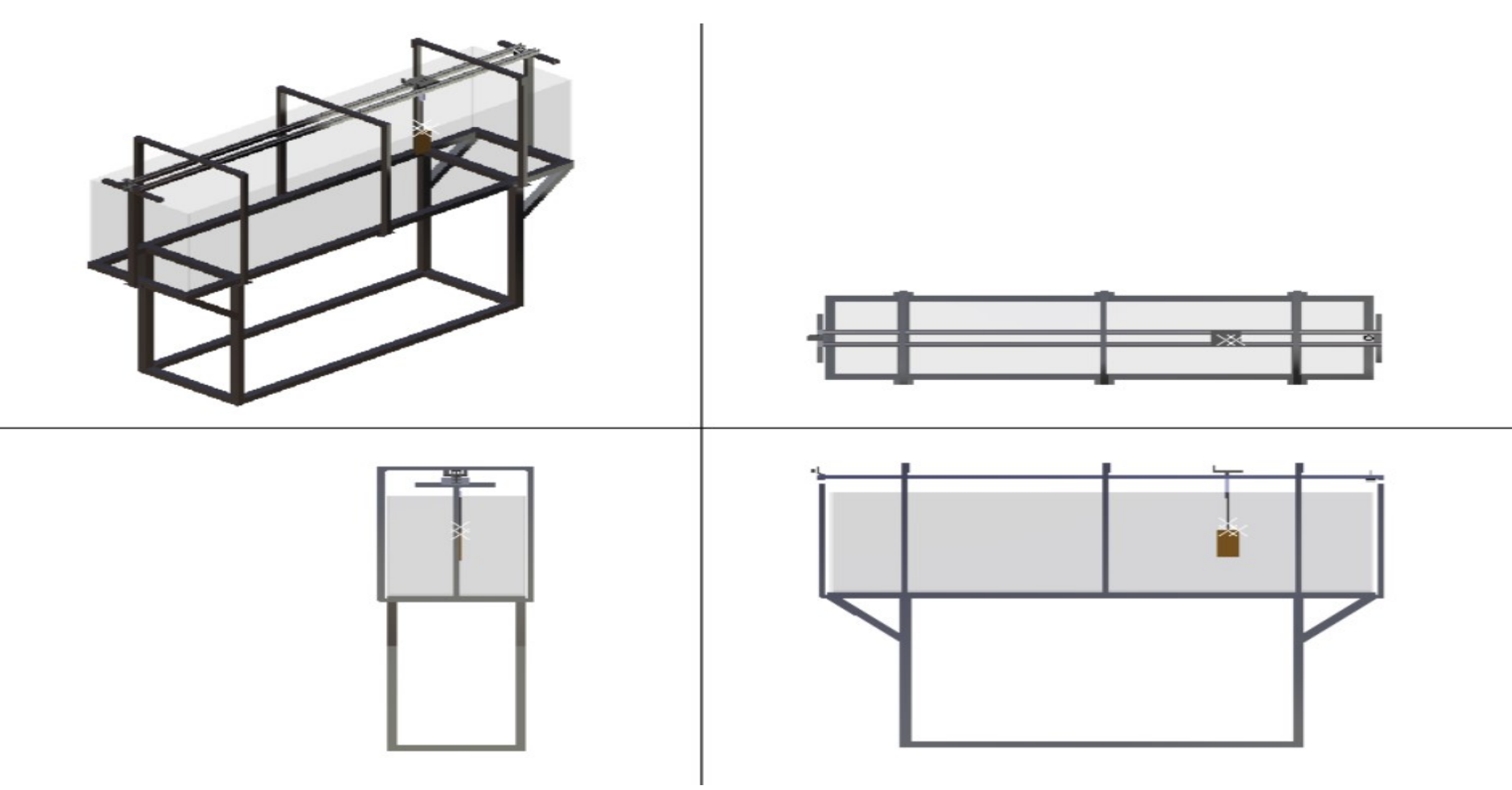
Fig: CAD assembly of frame and gantry
Optical System and Flow Seeding Strategy
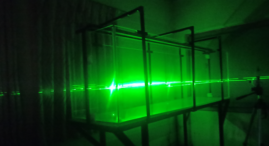
Planar laser illumination was generated using a Class IIIB 5 mW laser to produce a thin light sheet intersecting the measurement plane. Flow tracing was achieved using fine glass powder particles (less than 190 µm), selected after evaluating relaxation time and sedimentation velocity to ensure adequate flow-following capability under low-speed conditions. High-speed image acquisition was performed using a Chronos 2.1 camera (100 fps), while additional frame extraction was performed using a secondary imaging system for lower frame rate validation.
Image Processing and Velocity Reconstruction
Velocity fields were reconstructed using PIVlab (MATLAB-based FFT cross-correlation). Pre-processing included Contrast Limited Adaptive Histogram Equalization (CLAHE), high-pass filtering, and intensity normalization to enhance particle visibility and minimize noise contamination. Vector validation and spurious vector removal were applied to ensure reliable cross-correlation peak detection. The processing pipeline enabled accurate recovery of instantaneous velocity vectors and vorticity contours, even under low particle density conditions.
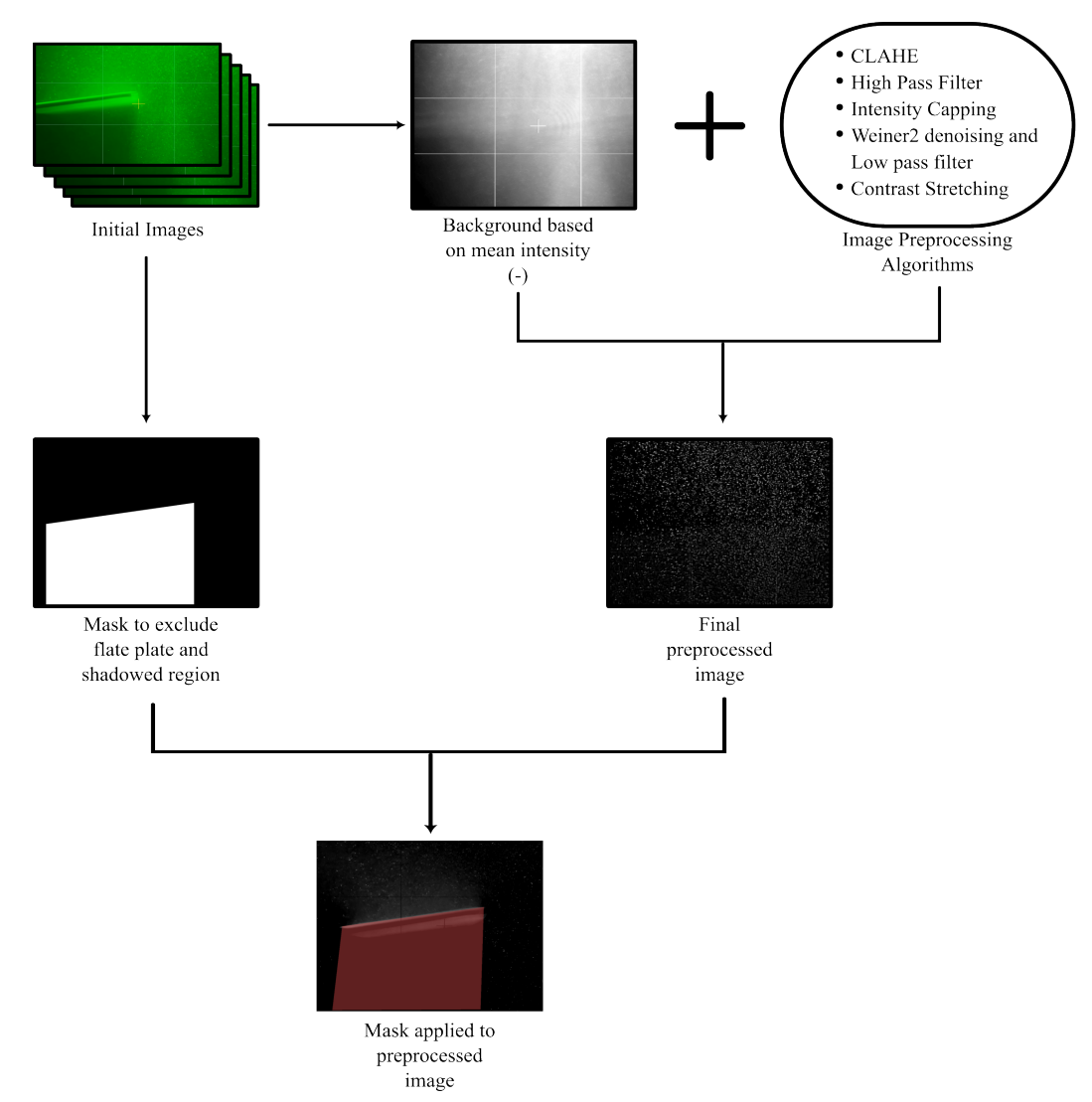
Fig: Image Pre-processing Flowchart
Experimental Investigation and Flow Physics
Two test configurations were investigated: a NACA 0012 airfoil (Re ≈ 3,270) and a flat plate (Re ≈ 6,040). The velocity vector fields revealed leading-edge vortex formation and laminar separation bubble behavior consistent with low Reynolds number aerodynamic theory. Vorticity contours showed coherent vortex shedding patterns downstream of the flat plate, indicating successful resolution of unsteady flow structures. Spanwise velocity variations and near-wall flow distortion highlighted three-dimensional effects and the limitations of quasi-two-dimensional assumptions. Experimental results were compared against ANSYS Fluent simulations to assess qualitative agreement in separation location and velocity distribution trends.
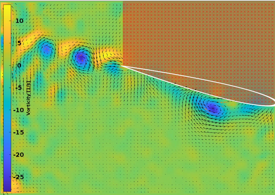
Fig: Velocity (m/s) field around aifoil and vorticity contour at α = 12 degree, airfoil moving from left to right (mask applied at shadowed region)
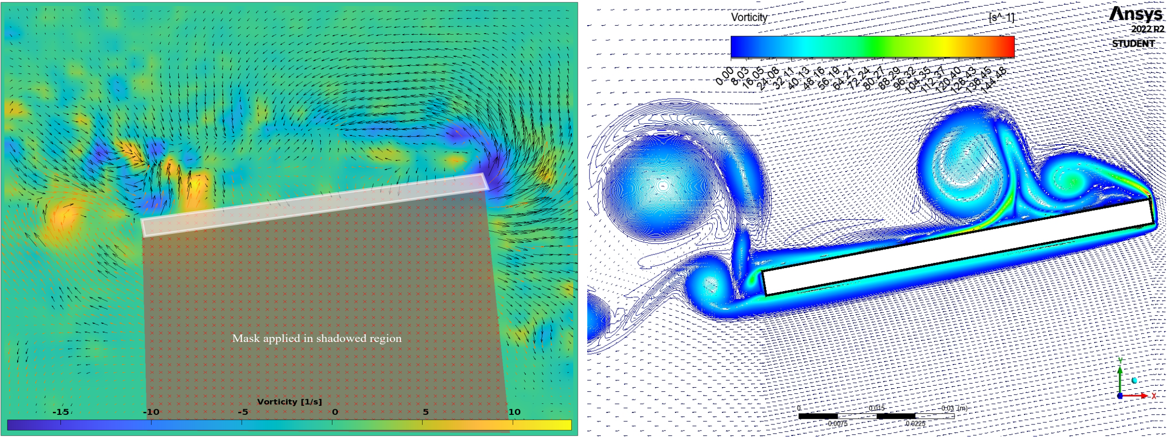
Fig: Velocity (m/s) vector field and vorticity contour at α = 12deg, flat plate moving from left to right (mask applied at shadowed region)
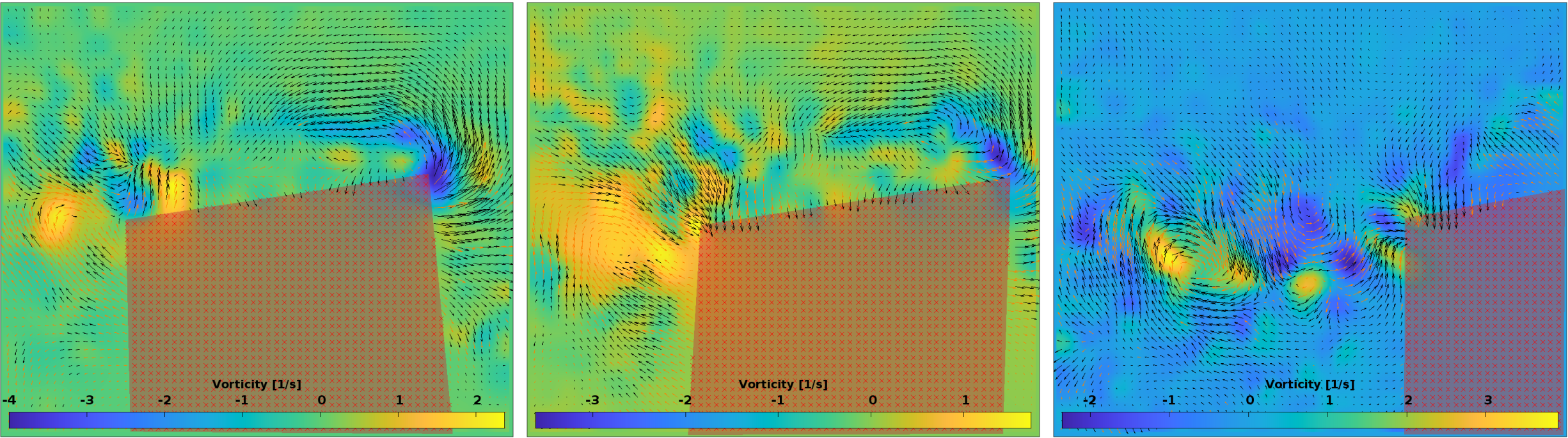
Fig: Vorticity contours around the flat plate, flat plate moving from left to right (mask applied at shadowed region)
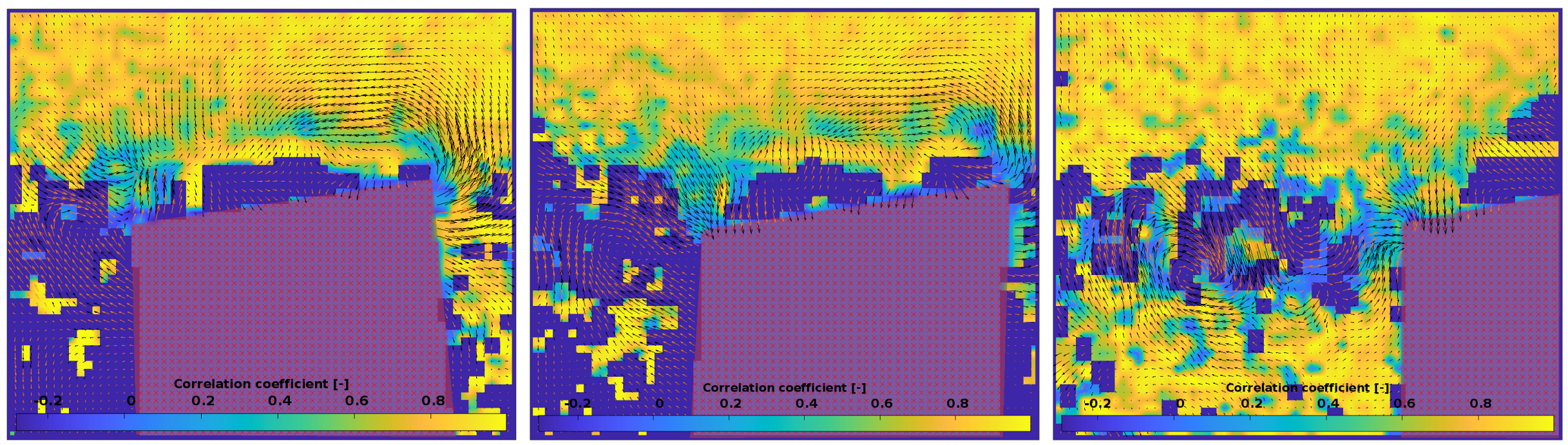
Fig: Correlation coefficient contour plot, flat plate moving from left to right (mask applied at shadowed region)
Uncertainty and Error Analysis
Measurement uncertainty was assessed based on particle size, interrogation window size, image resolution, and cross-correlation sensitivity. Primary error sources included illumination non-uniformity, particle sedimentation, optical distortion, and low signal-to-noise ratio at high displacement gradients. Despite these limitations, velocity trends remained consistent with theoretical and numerical predictions.
Technical Significance
This project demonstrates the ability to:
- Design and fabricate experimental fluid mechanics infrastructure
- Perform structural validation via FEA
- Implement optical flow measurement systems
- Conduct low Reynolds number aerodynamic experiments
- Apply digital image processing and FFT-based cross-correlation
- Validate experimental results against CFD simulations
- The fabricated system now serves as a reusable research platform for future investigations in unsteady aerodynamics and vortex-dominated flows.