Design Methodology
The design process began with preliminary mean-line analysis. A Python-based solver was developed to iteratively compute velocity triangles at the midspan by fixing the flow coefficient and loading coefficient. Free vortex radial equilibrium theory was applied to account for spanwise variations in whirl velocity. Using the specified mass flow rate, hub-to-tip ratio, and an assumed aspect ratio of 1.5, key aerodynamic parameters such as blade angles, axial velocity, degree of reaction, and rotor speed were calculated. The resulting rotor speed was approximately 11464 rpm with a tip radius of 0.2 m.
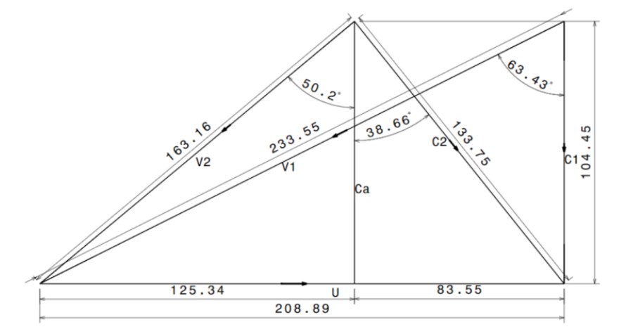
Fig: Velocity triangles at rotor midspan used for preliminary aerodynamic design.
Blade geometry was developed by constructing circular camber lines corresponding to the calculated flow angles at the hub, mean, and tip sections. A NACA 65-series airfoil (NACA 651212) was selected and superimposed on these camber lines to achieve an appropriate thickness distribution. The sections were stacked and smoothly blended in CATIA to generate the final three-dimensional blade geometry.
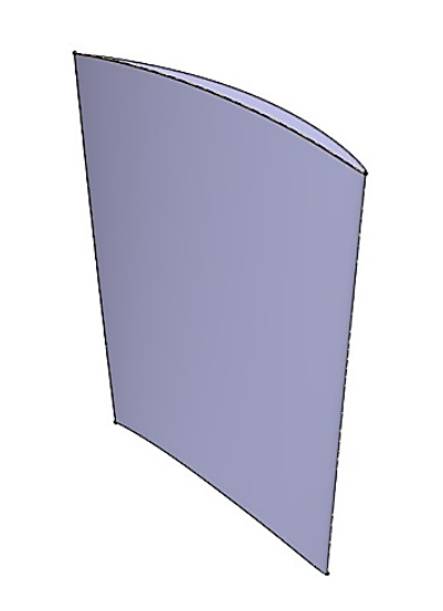
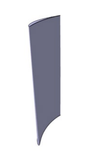
Fig: Final 3D rotor and stator blade geometry generated in CATIA.
Numerical Setup
Structured multi-block hexahedral meshes were generated in ANSYS TurboGrid using O–H topology to ensure adequate boundary-layer resolution. The final mesh consisted of approximately 496,000 nodes with near-wall y+ values around 20. A mesh independence study was conducted to confirm solution stability.
CFD simulations were performed in ANSYS CFX using the SST k–ω turbulence model. Both steady RANS simulations with a mixing plane interface and transient URANS simulations using a time transformation model were carried out to capture rotor–stator interaction effects.
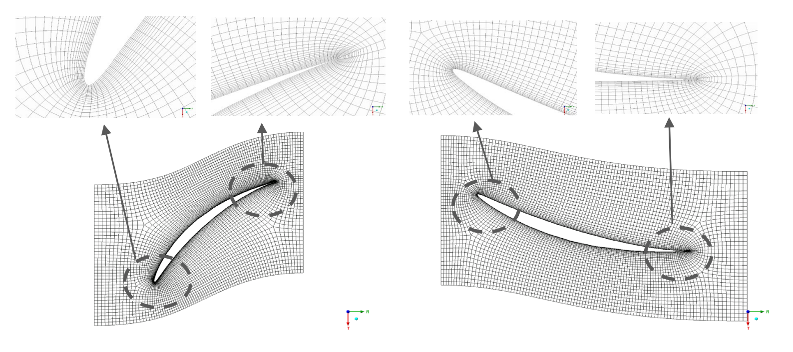
Fig: Structured O–H topology mesh generated in ANSYS TurboGrid.
Results
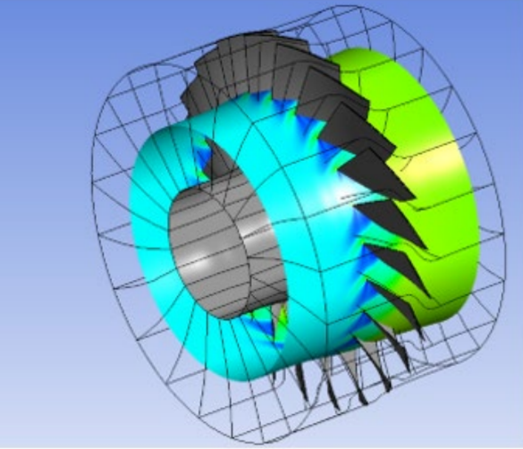
Steady-state simulations predicted a total pressure ratio of approximately 1.12 and an isentropic efficiency near 78 percent. Transient simulations revealed periodic pressure oscillations, with the pressure ratio varying between 1.13 and 1.17 due to blade row interaction. Although slightly below the target pressure ratio of 1.2, the results were achieved without geometric optimization, sweep, lean, or tip clearance modeling, demonstrating strong baseline aerodynamic performance.
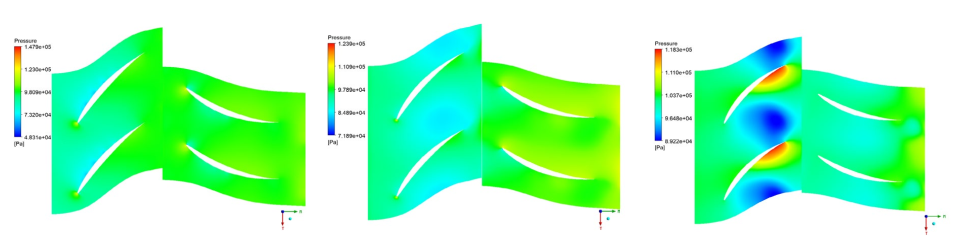
Fig: Pressure distribution across rotor–stator stage showing compression process.
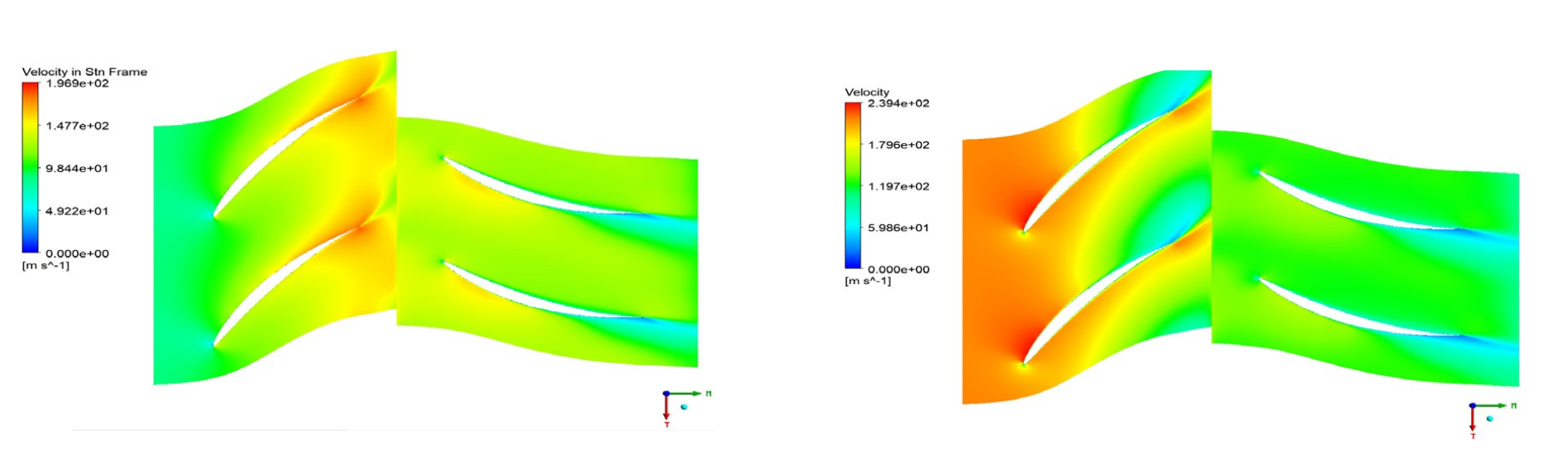
Fig: Contours of absolute and relative velocity across the stage.
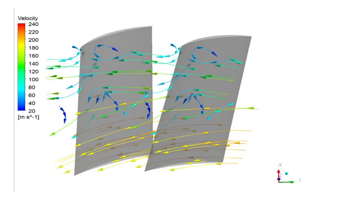
Fig: Secondary flow structures and passage vortex formation near endwall regions.
Flow Physics Observations
Flow visualization revealed the presence of secondary flows and passage vortices, particularly near endwall regions. The rotor increased the absolute velocity of the flow and imparted kinetic energy, while the stator diffused the flow and converted kinetic energy into static pressure. Spanwise analysis indicated that meridional velocity decreased toward the tip, highlighting deviations from the constant axial velocity assumption used in preliminary design. These findings emphasized the inherently three-dimensional and unsteady nature of axial compressor flow.
Technical Contributions
This project demonstrates proficiency in turbomachinery aerodynamic design, velocity triangle analysis, free vortex modeling, CAD-based blade generation, structured meshing, RANS and URANS simulation, mesh independence verification, and performance evaluation under realistic engineering constraints.