Design Requirements and Constraints
The design was governed by functional, structural, manufacturing, and economic constraints.
Key requirements included:
- Maximum trolley weight below 60 kg
- Multi-level storage configuration
- Safe containment of irregularly shaped exhaust pipes
- Rolling mobility using rubber wheels
- Welded steel structure for rigidity
- Compact footprint to minimize laboratory space usage The trolley needed to ensure structural integrity under static loading conditions while allowing easy access to stored components.
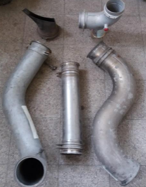
Fig: Aircraft exhaust stack components requiring structured storage.
Conceptual Design and Option Selection
Three distinct design configurations were developed and modeled in CATIA:
- Option A – Simplified open-frame structure
- Option B – Single-level platform with vertical support
- Option C – Two-storey reinforced structure with integrated casing
Quantitative comparison showed significant variation in mass and material usage:
- Option A: 108 kg (structurally inefficient)
- Option B: 45.6 kg (lighter but functionally limited)
- Option C: 54.5 kg (balanced performance and functionality) Qualitative evaluation revealed that Option A suffered from plate distortion under load, while Option B required external fastening mechanisms to secure components. Option C provided firm casing and superior structural behavior.
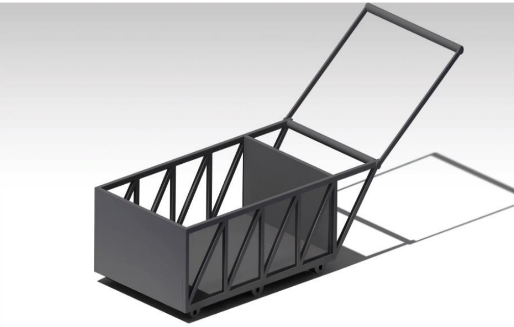
Fig: Design Option A
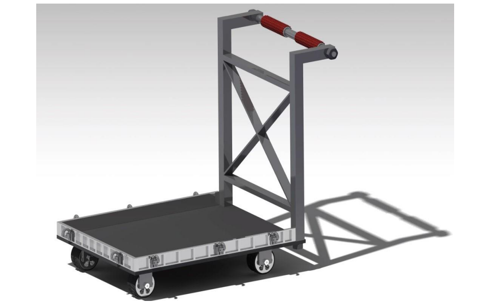
Fig: Design Option B
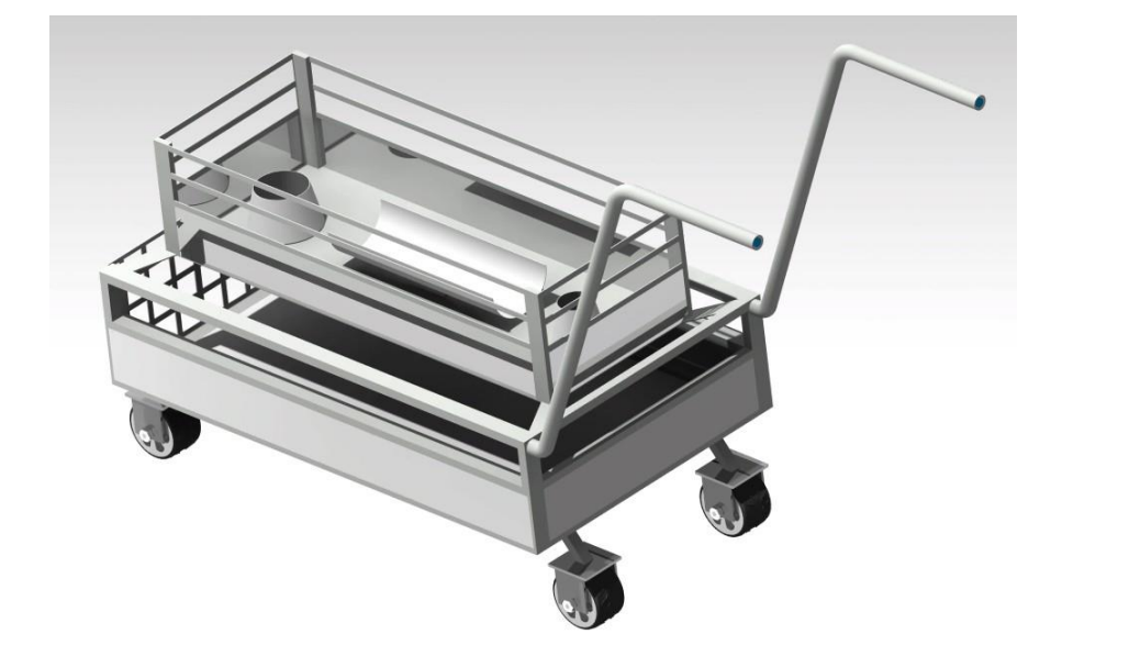
Fig: Design Option C
Structural Evaluation and Finite Element Analysis
Finite Element Analysis (FEA) was conducted to evaluate stress distribution and structural performance under applied loading conditions.
Option Comparison
- Option A exhibited stress concentration near wheel casings and plate distortion.
- Option B demonstrated limited load-bearing capacity and higher deformation.
- Option C successfully withstood applied forces, with stress concentrations localized at welded joints but remaining below material yield strength.
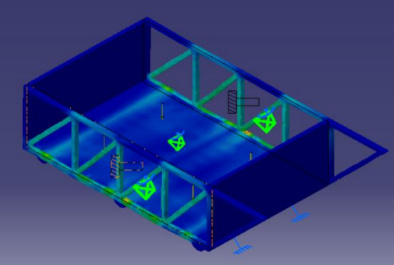
The Von Mises stress distribution confirmed structural adequacy of the selected configuration.
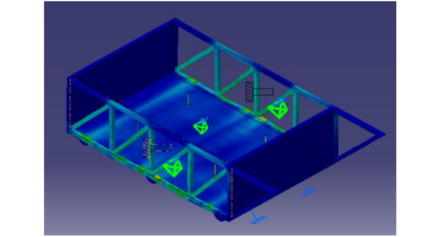
Fig: Option A Von Mises Stress
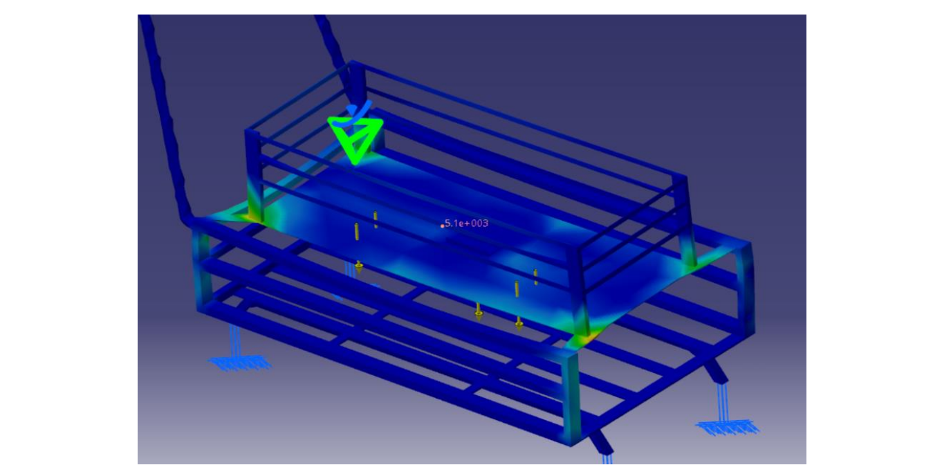
Fig: Option C Von Mises Stress
Preliminary Force Analysis
Member force analysis was conducted on the critical front frame region of the selected design. Static equilibrium calculations were used to determine internal forces under distributed component loading.
The analysis confirmed that the structural members operated within safe stress limits under expected service loads.
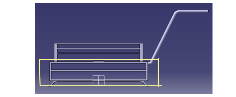
Fig: Highlighted Portion of Front View
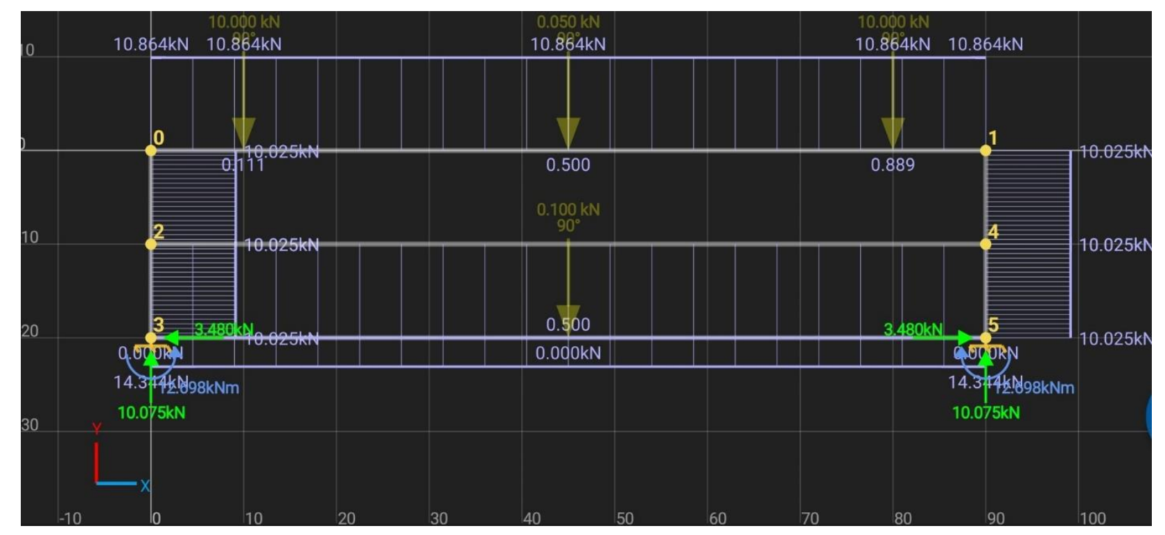
Fig: Force Analysis on Members
Stability and Transportability Assessment
Rotational stability was evaluated by analyzing the position of the center of gravity relative to the wheelbase. The trolley was found to topple only at an incline of approximately 55 degrees, indicating high resistance to overturning.
Additionally, push-force requirements were calculated using rolling friction analysis. Assuming a rolling friction coefficient of 0.015 and total mass of 54.5 kg, the trolley can be transported on an incline of approximately 12 degrees with an applied force of 120 N, which falls within average human capability.
This analysis demonstrates real-world usability validation.
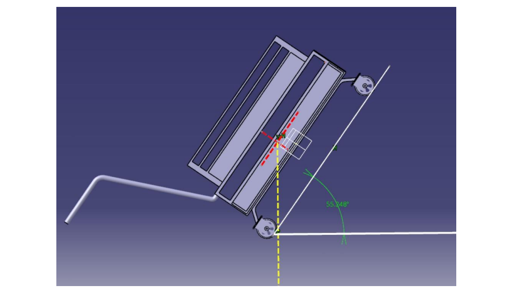
Fig: Rotational Stability in Inclined Surface
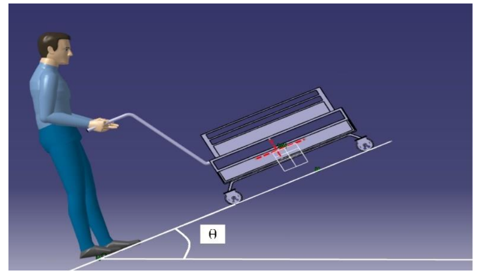
Fig: Transporting Trolley Over Incline Plane
Deflection and Structural Integrity
Deflection analysisf showed negligible deformation under typical service loads. Minor deflection was observed only under exaggerated loading scenarios, confirming structural stiffness and adequacy of truss configuration.
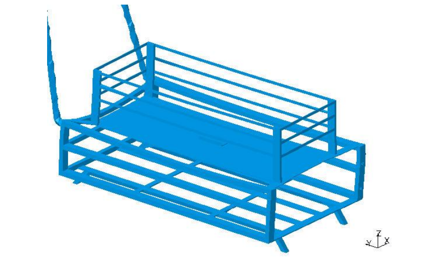
Fig: Deflection behavior under applied load conditions.
Detailed Design and Manufacturing Considerations
The final design consists of:
- Steel rectangular bar frame (45 kg)
- Aluminum sheet panels (7 kg)
- Rubber caster wheels
- Hinged locking mechanism
The design prioritizes welding over bolted joints to improve stress distribution and rigidity.
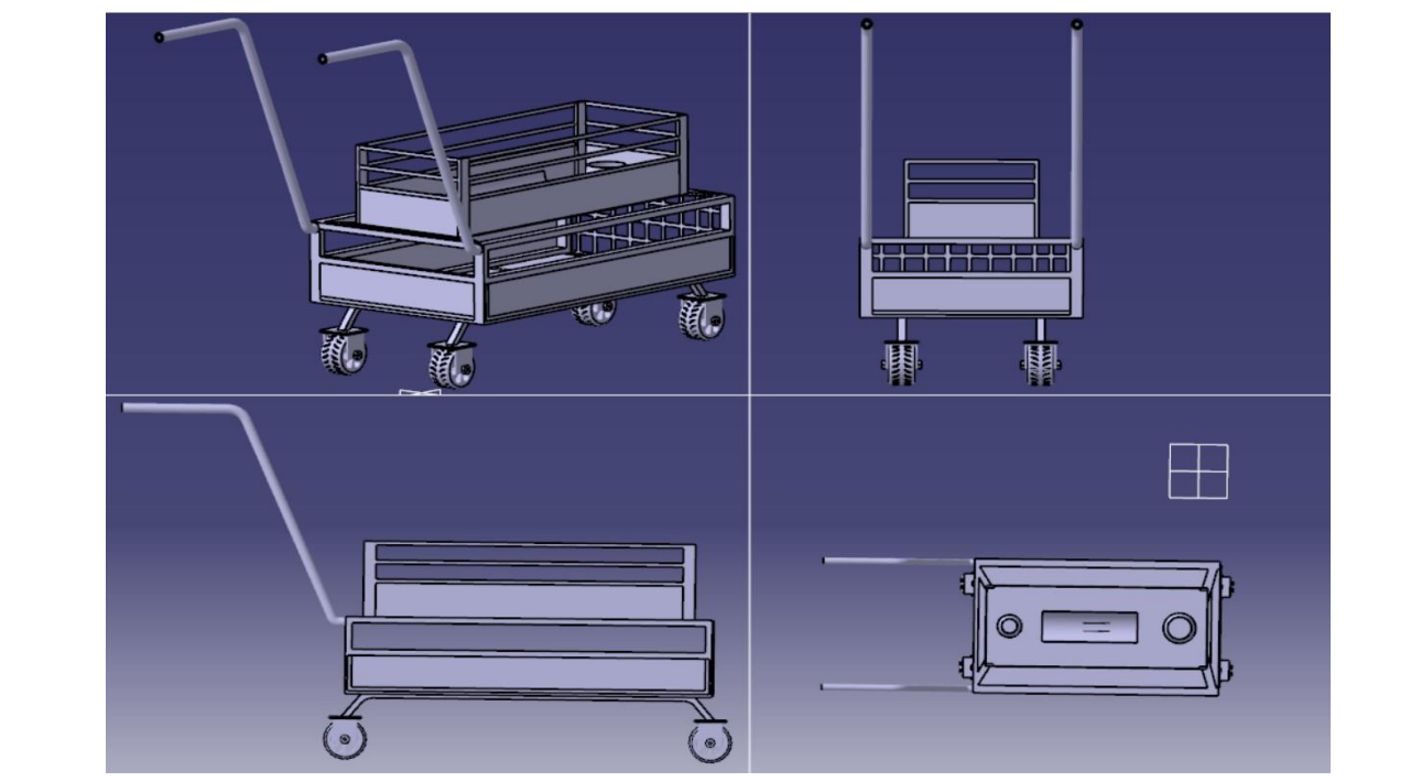
Fig: Orthographic views of finalized trolley design.
Cost Analysis
Material and component costs were calculated through a Bill of Quantity. The estimated total manufacturing cost was approximately Rs. 15,840, including fabrication.
This confirms economic feasibility alongside structural adequacy.